本公司其它产品
品牌名称:
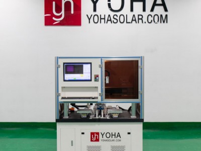
Product Introduction
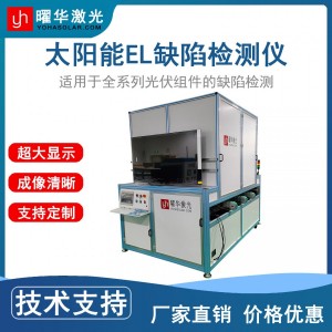
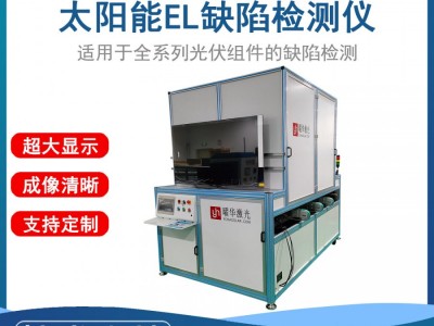
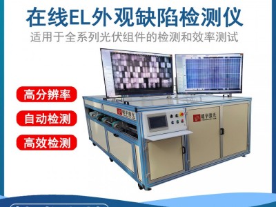
The Top-Shooting PV Module EL Defect Tester is an automated optical inspection device based on the electroluminescence principle, designed with a top-down imaging structure. It non-contactly and rapidly captures weak near-infrared light images emitted by internal solar cells of PV modules after current application, thereby identifying various internal defects that affect module performance and reliability, such as microcracks, fragments, grid breaks, black cores, black spots, sintering defects, process contamination and PID attenuation.
Product Features
Core Function: Non-Destructive Internal Defect Detection
The device utilizes the electroluminescence (EL) principle to pass current through PV modules in a darkroom environment, causing the solar cells to emit near-infrared light.A high-sensitivity camera captures such luminescence images, intuitively displaying micro-internal defects of solar cells—including microcracks, grid breaks, black cores, black spots, fragments, sintering reticulation, process contamination and low-efficiency cells—that are difficult to detect with the naked eye or conventional testing methods.
Key Feature: Top-Shooting Design
Different from the traditional method where modules need to be flipped or cameras shoot from below, the top-shooting design places a high-resolution camera directly above the tested module.Modules are usually placed horizontally or slightly tilted on the test platform, with the camera shooting from top to bottom. This design simplifies the operation process, reduces module handling and flipping, lowers the risk of damage, and is easier to integrate into automated production lines.
High Precision & Automated Integration
Equipped with a high-resolution infrared camera and optical lenses to ensure clear imaging and identification of subtle defects.It usually integrates a motion platform to realize automatic positioning and scanning of modules.Configured with a current source to accurately control the magnitude and direction of current injected into the module (forward bias for EL imaging).Built-in image processing software can automatically analyze EL images, identify, classify and mark defects, and generate inspection reports.
Core Value: Improve Quality & Efficiency
Ensure Module Quality
Strict screening during production (e.g., before/after lamination) or ex-factory inspection prevents defective modules from entering the market, ensuring product performance and long-term reliability.
Optimize Production Processes
Trace the root cause of problems through statistical analysis of defects, and guide the improvement of process links such as solar cell manufacturing, welding and lamination.
Boost Production Efficiency
High-speed automated detection reduces reliance on manual labor, meets the high-speed beat requirements of production lines, and lowers comprehensive inspection costs.
Technical Parameters
| Item | Specification |
|---|---|
| Model | YHEL-S2400 |
| Applicable Processes | Defect detection of modules before and after lamination |
| Test Specifications | Monocrystalline and polycrystalline solar modules |
| Camera Type | Yohasolar Customized Camera |
| Resolution | EL: 24MP / 60MP |
| Shooting Mode | Single/Multi-camera mode |
| Sensitivity | Capable of detecting cracks with width < 0.03mm |
| Effective Test Area | 2600*1500mm |
| Regulated Power Supply | 60V/20A |
| Image Acquisition Time | 1~60s (adjustable) |
| Power Supply | 220V/50HZ |
| Equipment Dimensions | 2900×1940×1155mm |
Product Applications
Production Line Quality Control: Conduct online or offline detection on PV module production lines. Used for 100% inspection or sampling inspection of modules after production, it quickly detects internal defects such as solar cell microcracks, fragments, grid breaks, cold solder joints, black cores, black edges and process contamination, ensuring the quality of ex-factory modules meets standards.
Laboratory R&D & Process Optimization: In R&D laboratories, it is used to evaluate the impact of new materials, new processes and new structures (e.g., new cell technologies, different welding methods, different packaging materials) on module reliability and performance. Comparative analysis of EL images provides key basis for process improvement and product design optimization.
Incoming Acceptance Before Power Plant Construction: Conduct unpacking sampling or 100% inspection on modules delivered to the site before PV power plant installation. It is used to identify damages such as microcracks and breakage caused during transportation or handling, verify whether module power and quality meet contract requirements, ensure the basic quality of the power plant, and prevent inferior modules from being installed.
Power Plant O&M & Fault Diagnosis: Used for regular patrol inspection or fault location after the operation of PV power plants. EL detection can find defects generated during operation such as hot spots, PID attenuation, microcrack expansion, welding aging and diode failure, locate problematic modules, guide maintenance and replacement, and improve the power generation efficiency and service life of the power plant.
Precautions
Strict Darkroom Environment Assurance: Ensure a completely dark inspection environment (e.g., darkroom or closed inspection chamber); any external light source (including red light) will interfere with EL imaging. The airtightness of the darkroom door must be checked regularly to avoid increased image noise caused by light leakage.
Standard Module Placement: The tested module must be fully attached to the test platform; suspension or tilting will cause blurry imaging and edge distortion. The module surface must be clean and unobstructed (e.g., no dust or obstructions) to avoid misjudgment as defects.
Operational Protection Measures: Module Electrification Risk: EL detection requires applying voltage (usually 40~60V) to the module; operators must wear insulating gloves and the device must be reliably grounded. Mechanical Protection: When the automatic transmission type equipment is in operation, it is forbidden to put limbs into the area of moving parts (e.g., rollers, robotic arms).
Equipment Optical System Maintenance: Regularly clean the camera lens and infrared filter (using professional dust-free cloth and cleaning agent); fingerprints or dust will reduce imaging clarity.
Parameter Adaptation & Calibration: Current/voltage parameters must be dynamically adjusted according to module type (monocrystalline/polycrystalline/thin-film) and power; excessively high voltage may damage solar cells, while excessively low voltage fails to stimulate luminescence. Calibrate the equipment with a standard calibration plate regularly to ensure the accuracy of defect identification (e.g., microcrack size measurement error ≤ 0.03mm).
Environmental Temperature & Humidity Control: The recommended operating temperature is 10~30℃; excessively high temperature may cause equipment overheating and shutdown, while excessively low temperature affects camera sensitivity. Humidity should be controlled at 30%~70% to avoid condensed water vapor adhering to the lens or causing circuit short circuit. Avoid colliding with the camera bracket to prevent lens focus shift from affecting imaging accuracy.

-

面议
立即询价 -

面议
立即询价 -
面议
立即询价
